
A cabinet LED lighting plan is incomplete when it shows the glow but hides the driver. Every illuminated shelf, wardrobe rail or plinth should connect to an exact voltage, calculated load, compatible driver and control, cable route, ventilated location, removable access and named electrical responsibility.
Integrated lighting crosses two packages. Cabinet drawings control grooves, profiles, holes, removable panels and the relationship to doors and shelves. Electrical design controls mains supply, protection, switching and destination requirements. A useful handoff makes that boundary visible instead of writing “LED by others” beside a finished rendering.
Give each run a stable identity: island plinth, left display shelf, wardrobe hanging rail, tall-unit vertical profile or another real location. Record purpose, operating hours, switching group, colour specification, diffuser/profile, length and whether the source is replaceable without damaging the cabinet. Do not combine visually similar runs when they use different voltages, controls or service routes.
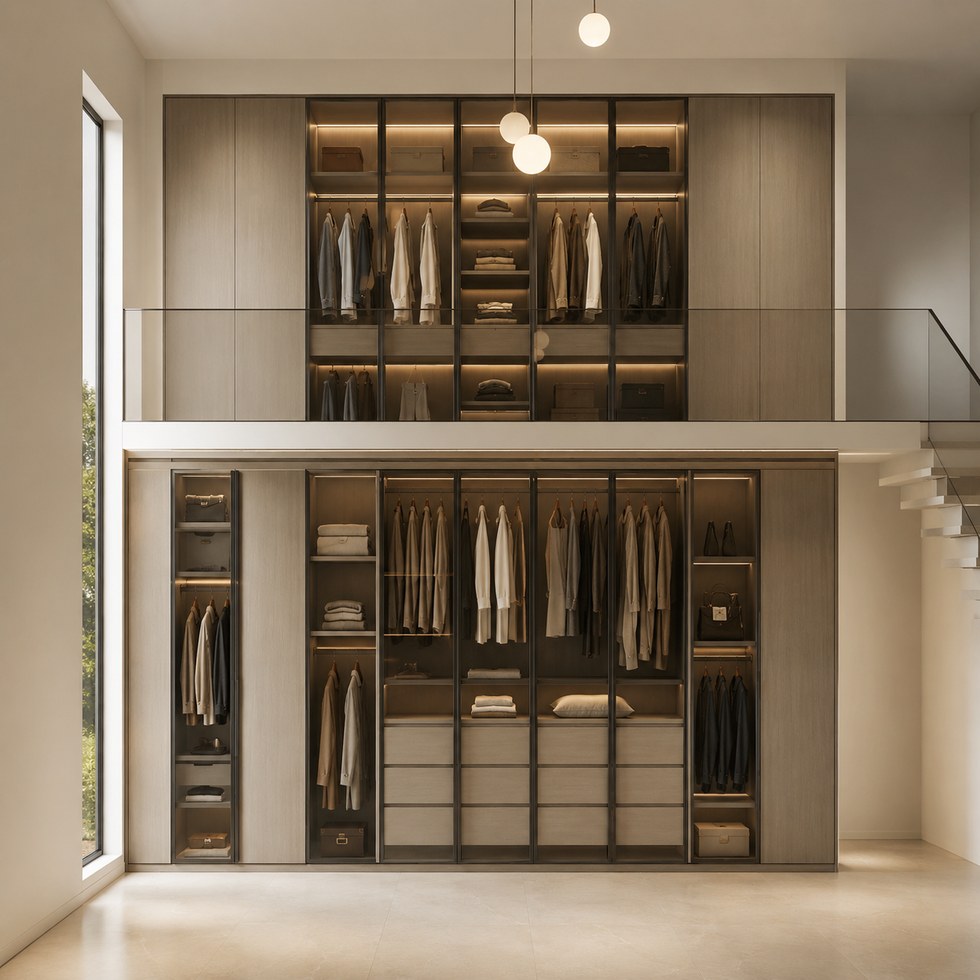
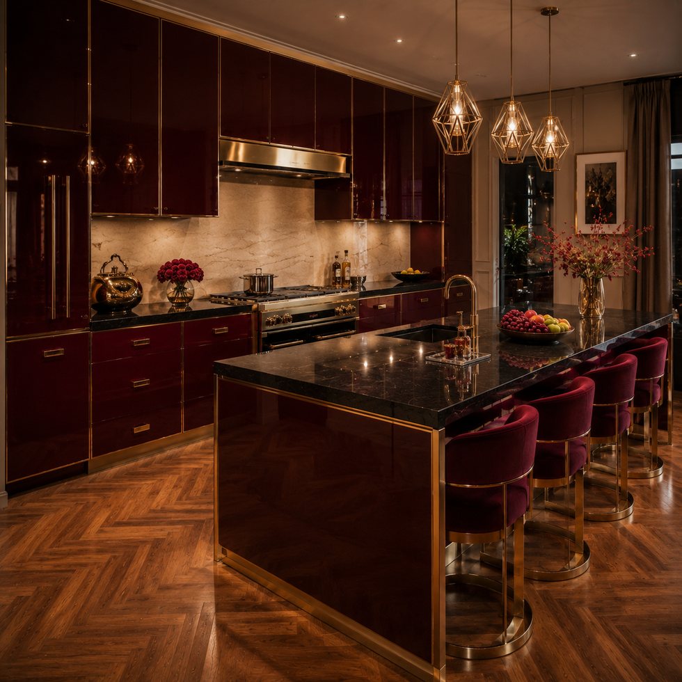
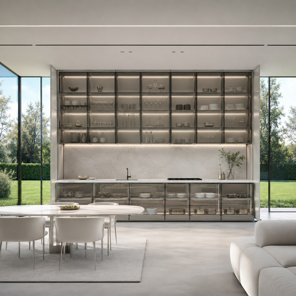
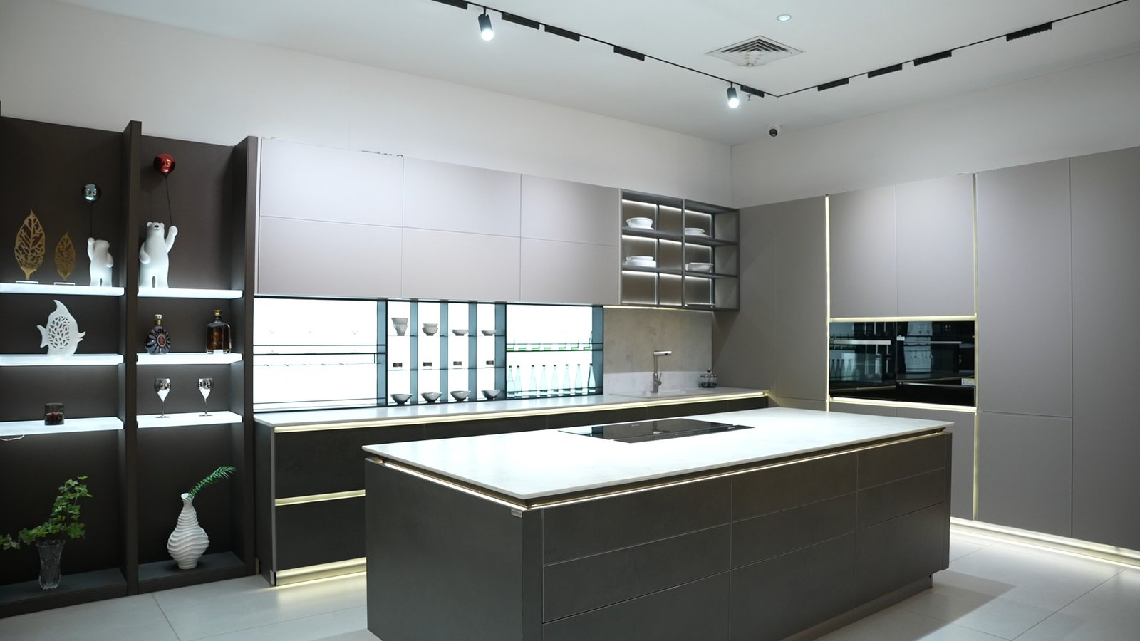
The owned showroom image above contains shelf, vertical and plinth lighting in one room. That variety is exactly why a single note cannot control the system. A dim decorative shelf and a work-area strip may need different output, distribution and control even when both appear as continuous lines in an elevation.
List the exact light and lead for every zone, then calculate connected wattage from the selected product data and length. Group only compatible voltage and control types. Record the driver model, rated output, intended design margin, distributor and port assignment. The calculation should be easy to update when a strip length or accessory changes; it should not rely on the driver label being photographed after installation.
The Häfele Loox design guide treats drivers, distributors and extension leads as a connected system and gives model-related lead-length limits. Its 12 V driver entry warns that long leads combined with large loads can cause voltage loss and visible brightness reduction. Those figures apply to the cited system; use the selected manufacturer's data for the project.
A driver should not disappear permanently behind a fixed back, glued wall panel or stone return. Draw its mounting orientation, surrounding clearance, ventilation path, access opening and removal direction. Confirm that a technician can isolate power, see the label, reach terminals or plugs and remove the unit without dismantling unrelated cabinet modules.
Thermal conditions are product-specific. The cited Häfele driver requires adequate air supply and circulation at the mounting location and states its ambient-temperature information. Mean Well's LED power-supply installation manual requires power isolation before work and instructs installers to provide ventilation, observe model-specific mounting orientation and review derating under higher ambient temperature. Do not copy one manufacturer's clearance into another driver's cabinet detail.
Map holes, grooves, connector heads, bend space, moving hinges and runners, removable shelves, appliance voids and panel joints. A cable can clear a closed door but be pinched during hinge adjustment. A plug may pass through the specified drill hole but become trapped when neighbouring modules are joined. Show where extra lead is retained and how it is prevented from entering drawer or hinge movement.
Lutron's Lumaris instructions recommend temporarily wiring and positioning the light for review before permanent mounting, then locating the driver according to its own instructions. That sequence is useful for cabinetry: test light distribution, connector access and cable concealment before closing grooves and backs.
Identify who provides the branch circuit, outlet or hardwired connection, isolation, required protection, switching interface and final connection. Then identify what the cabinet supplier provides: profiles, lights, compatible low-voltage leads, holes, channels, driver shelf or removable access panel. The destination electrician must confirm applicable rules and suitability; a cabinet drawing is not an electrical approval.
UL identifies UL 8750 as the standard for LED equipment used in lighting products. UL's discussion of wired controls in LED drivers also shows that control circuits are part of the evaluated system, not an interchangeable decorative afterthought. Certification evidence for one component does not establish that the complete installed cabinet system meets every destination requirement.
| Field | Record for each circuit section |
|---|---|
| 1. Light zone | Cabinet ID, purpose, profile, light model, colour and length |
| 2. Electrical match | Voltage, control type, connected wattage and design basis |
| 3. Driver | Exact model, output, ports, distributor and assigned zones |
| 4. Supply and control | Outlet or connection, isolation, switch, sensor and responsible trade |
| 5. Cable route | Lead type and length, holes, connectors, protection and moving conflicts |
| 6. Driver access | Location, orientation, ventilation, removable panel and extraction path |
| 7. Handover | Test result, labels, settings, spare references and replacement owner |
Use the VSME kitchen cabinet range or walk-in wardrobe systems to identify the actual cabinet zones. Lighting remains an adjacent function: the cabinet layout, storage access and installation interfaces still determine whether the solution is useful.
Before closing access panels, verify each zone against the map: correct light, steady output, intended switching or sensing, no visible connector strain, no clash with moving hardware and reachable driver identification. Record the installed driver, distributor ports and control settings. Photograph hidden routes only after confirming that the image contains no unrelated private site data.
Leave a service record with cabinet IDs, product references, circuit mapping and removal steps. A future technician should be able to isolate one section and replace its driver or light without guessing which wall panel to remove. If a driver, strip length, control or destination requirement changes, update the connected-load and compatibility check instead of treating the new part as a like-for-like cosmetic substitution.
Send VSME the cabinet elevations, named light zones, selected light and control references, outlet locations and destination electrical brief. Ask for the driver schedule, cable map and removable service route before production.
Related guide: Who we are, our minimum order and lead time: VSME company facts.