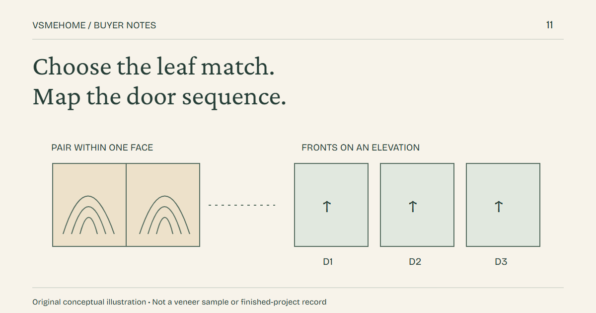

TV wall unit cable management starts with a service route, not a round hole behind the screen. List every device, locate its power and signal connections, draw the connector heads and cable bends at full size, then prove that heat can escape and each device can be removed without dismantling the wall unit.
A clean front elevation hides the difficult part. The television may be shallow, while a side-facing HDMI plug, power connector or wall-mount arm occupies much more depth. A game console or receiver may fit inside a cabinet but overheat with the door closed. A cable path can also be invisible and still be unusable if the plug cannot pass through it.
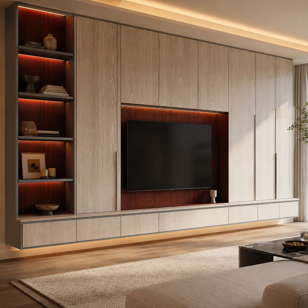
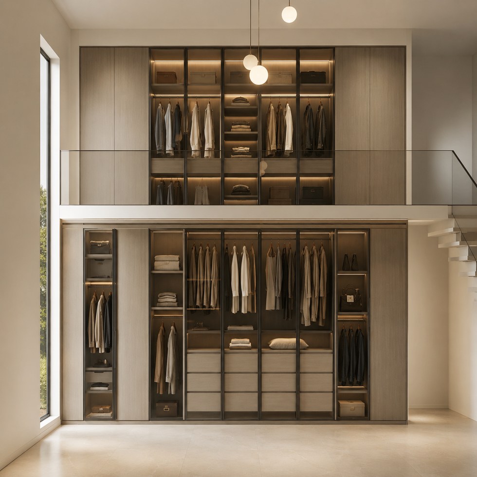
VSME product image. The finished wall unit shows the visible composition; it does not reveal the project-specific sockets, cable bends, ventilation path or access panels behind it.
Record the exact television, mount, soundbar, set-top box, router, game console and any control hub. For each item, note overall size, connector position, plug direction, ventilation instruction, remote or wireless requirement and replacement path. “TV point at centre” is not enough because two televisions of the same diagonal size can place power and HDMI connections on different edges.
Separate confirmed equipment from allowances. If the receiver model is not selected, reserve a labelled equipment zone with a maximum envelope, expected load and responsible party. Do not cut a device-specific opening around an unspecified future product.
The cabinet supplier can coordinate openings, removable panels and equipment space, but the project electrician must design and install the fixed electrical work for the applicable jurisdiction. England's Approved Document P frames dwelling electrical design around protection from fire and injury and calls for enough information to operate, maintain or alter the installation safely. That makes the as-built socket and circuit record part of the handover, not an afterthought hidden behind joinery.
Do not turn a flexible extension lead into the permanent plan. WorkSafe New Zealand describes extension cords as temporary and advises asking a licensed electrician to install a socket where permanent power is required. Local rules differ, so the drawing should identify the jurisdiction and electrician rather than copying one country's socket detail into every project.
A cable line on an elevation has no thickness. The real route includes the HDMI or data connector head, strain relief, minimum bend, conduit adapter and the hand movement needed to plug it in. At every turn, draw the cable envelope in section and confirm that the route remains clear after wall panels, mounting rails and back panels are installed.
An Extron wallplate installation guide tells installers to allow box depth for the wallplate and cables, account for cable bend radius and avoid forcing the cited cables through a 90-degree bend. It is a product-specific AV instruction, not a universal dimension. The useful rule is to obtain the selected cable and connector requirement before approving the cavity depth.
Conduit can provide a replaceable route only when the pull path works. Test the internal diameter against the largest connector, not just the cable jacket, and record draw-wire access, bend locations and both endpoints. A conduit that disappears behind a fixed panel is not serviceable.
Do not copy one decorative grille onto every TV cabinet. Heat must travel from the device intake to an outlet without being trapped by a closed door, shelf edge or cable bundle. The final calculation depends on the chosen equipment, cabinet volume, openings and room conditions.
For one current example, Samsung's wall-mount guidance asks for at least 10 cm around the top, bottom and sides of the referenced television for ventilation. That value should not become a universal media-wall clearance. Read the final television and AV manuals, apply the most restrictive relevant instruction and keep vents clear after accessories are installed.
Put the route in one table linked to plan, elevation and section details. The aim is not more paperwork; it is to stop one trade from hiding the only access another trade needs.
| Item | Map before release | Proof |
|---|---|---|
| Television | Mount pattern, connector side, screen removal and ventilation zone | Model manual and wall section |
| Fixed power | Socket position, circuit responsibility and accessible isolation | Electrician's coordinated drawing |
| HDMI, data and coax | Endpoints, largest connector, bends, conduit and spare pull path | Route section and pull test |
| AV equipment | Shelf envelope, airflow, door state and control signal | Equipment schedule and heat path |
| Service access | Panel fasteners, removal direction, hand space and finish protection | Removal-sequence sketch |
A recessed commercial kit can help the team discuss interfaces, but it must not be copied blindly. The Legrand CPT306WV1, for example, is a specific North American product that combines two recessed power outlets with cable access for HDMI, coax and Cat 5e. Its dimensions, listings and installation method belong to that product and market. Use it as evidence that power and low-voltage access need an identified system, not as automatic approval for another country.
Run the sequence in reverse. Can the television lift off the mount without hitting the top panel? Can a right-angle plug be disconnected before the screen moves? Can the access cover leave the opening after shelves, lighting and stone finishes are installed? Can a router be replaced without removing a fixed countertop?
Mark every removable panel on the drawing and identify its fastener, edge clearance and safe storage position during service. A push latch may look clean but still fail if the panel has nowhere to travel. The same check should include future cable replacement: a spare conduit is useful only if both ends remain reachable.
The factory can machine approved openings, label panels, preassemble cabinet sections, confirm removable-panel fit and compare the joinery to the issued route drawing. It cannot certify the site's concealed wiring, select a compliant circuit for an unknown jurisdiction or prove the ventilation performance of equipment that has not been named.
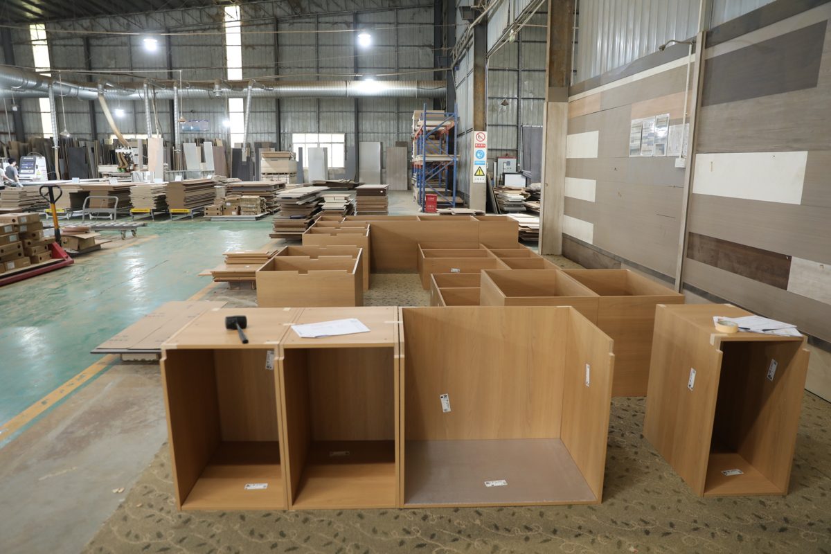
VSME factory photograph showing general cabinetry preassembly and identity checking. It is not a photograph of the TV wall above and does not prove its site wiring, cable route or thermal performance.
Use the VSME TV wall panel cabinet range to define the visible product scope and the broader TV cabinet category to compare storage formats. Then attach the service-route map, selected equipment schedule and electrician's drawing to the quotation request.
Hold production when a device is unnamed, a connector bend is shown only as a line, a ventilation opening ends inside another closed volume or an access panel cannot be removed. Those are design inputs, not problems for the installer to discover after the finished panels arrive.
Send the television and AV equipment schedule, wall section, fixed-power drawing, cable endpoints, connector dimensions, ventilation instructions and panel-removal sequence with the TV wall enquiry.
Related guide: Who we are, our minimum order and lead time: VSME company facts.